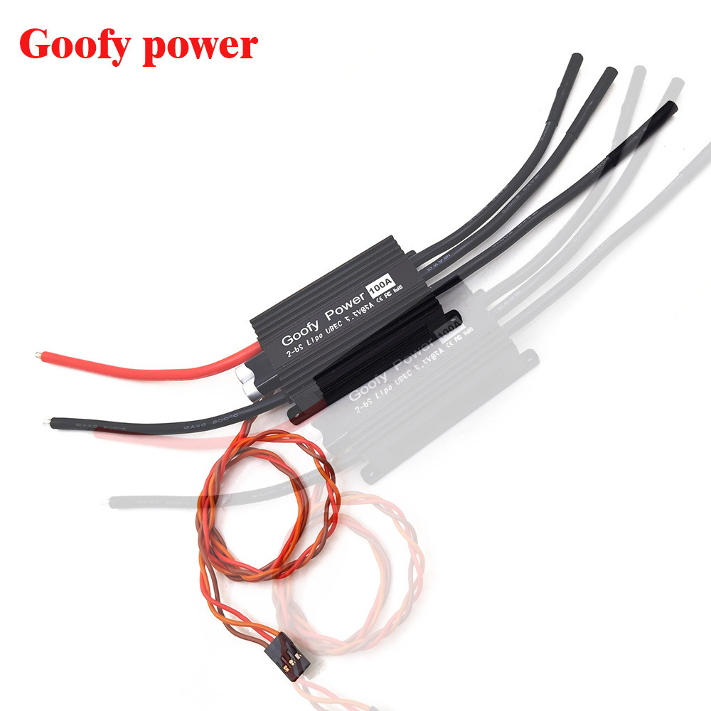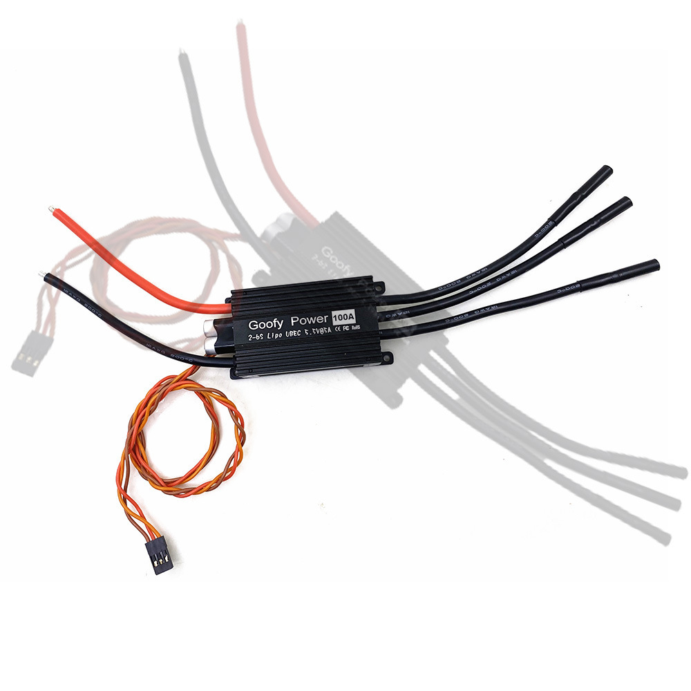
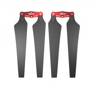


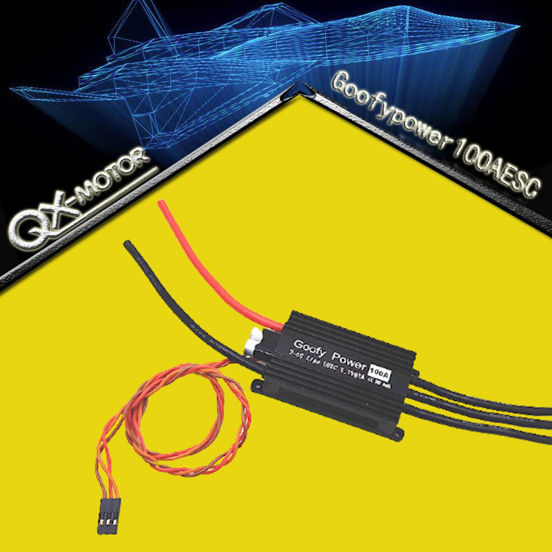
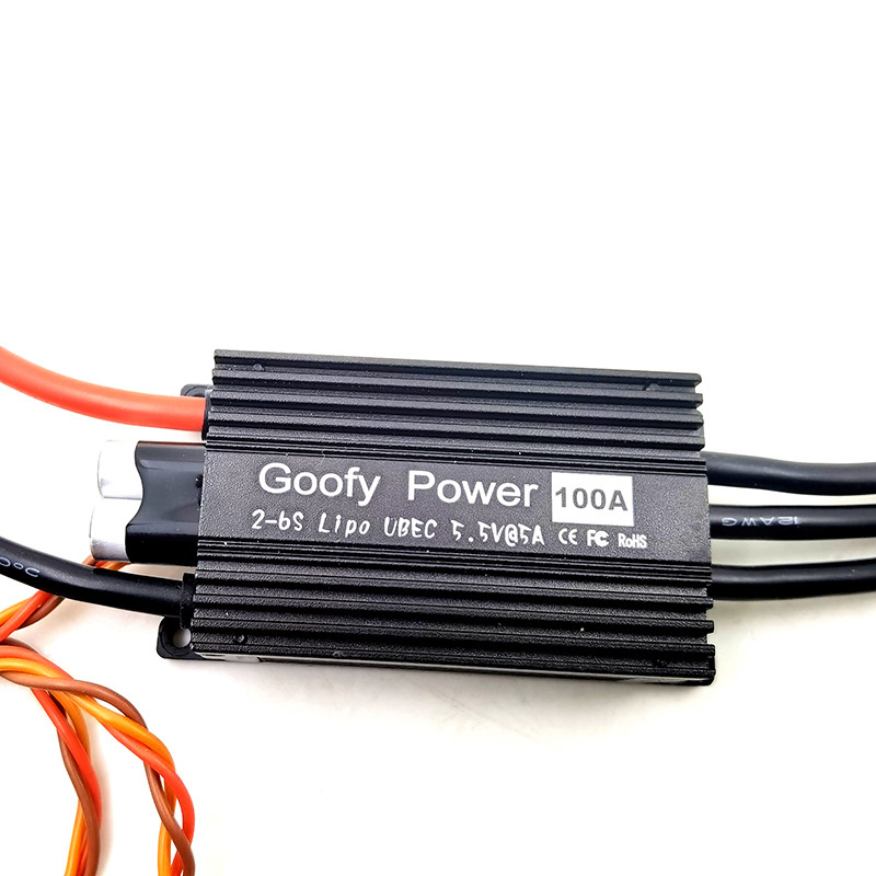
Electric regulation Goofy power2-6S100AModel aircraft electronic governor QX aircraft model accessories
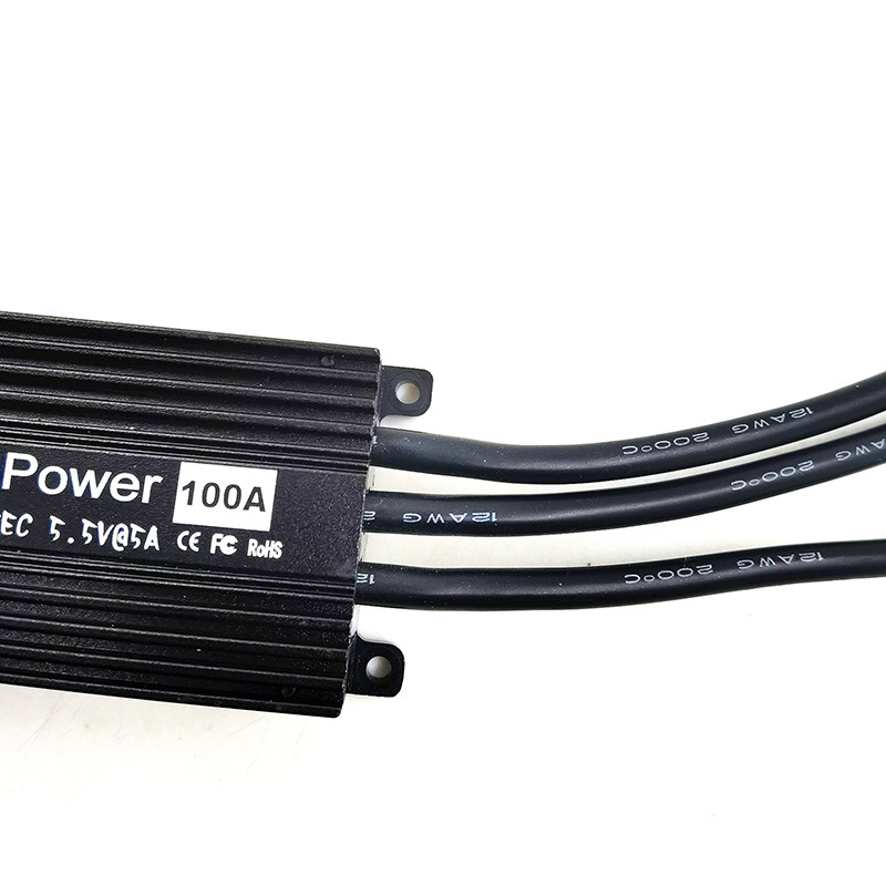
statement Thank you for purchasing this product! The power of brushless power system is powerful, and incorrect use may cause personal injury and equipment damage. Therefore, we strongly recommend that you read this manual carefully before using the equipment and strictly abide by the specified operating procedures. We are not liable for any liability arising from the use of this product, including but not limited to the liability for incidental or indirect losses; At the same time, we do not assume any responsibility caused by unauthorized modification of the product. We have the right to change the product design, appearance, performance and use requirements without notice. Product features 1. It adopts 32-bit ARM processor, which has the advantages of small volume, fast running speed and light weight. 2. High throttle acquisition accuracy and good throttle linearity. 3. It has the functions of synchronous rectification, active braking and energy recovery, which is more energy-saving than ordinary electric regulation of the same level. 4. Support and automatically identify common remote control signals, and the throttle stroke can be set to be compatible with different remote controls. 5. The motor has good compatibility and can adapt to most motors on the market. 6. The supporting programming card realizes the integration of multiple functions, is specially tailored for fixed wing aircraft, has complete independent intellectual property rights, and the products can be continuously upgraded and updated. Parameter specification 1. The output power of electric regulation is 100A. 2. Peak current 120a. 3. The number of lithium batteries supported is 2 ~ 6S. 4. Support BEC output, and the 5-8v / 10A BEC programming card is adjustable. 5. The output PWM frequency is 8-32khz, and the frequency is adjustable by the programming card. 6. The throttle range of ordinary remote control signal is 900us ~ 2400us. 7. Maximum supported speed: 300000 RPM (2 magnetic poles), 100000 RPM (6 magnetic poles), 50000 RPM (12 magnetic poles). 8. Weight: 116g. 9. Size 65 * 38 * 20MM. 10. When the controller makes an error during operation, it will make a sound on the motor. The fault will not be saved, and the error will lead to shutdown. After power failure and reset, the fault alarm sound will be cleared
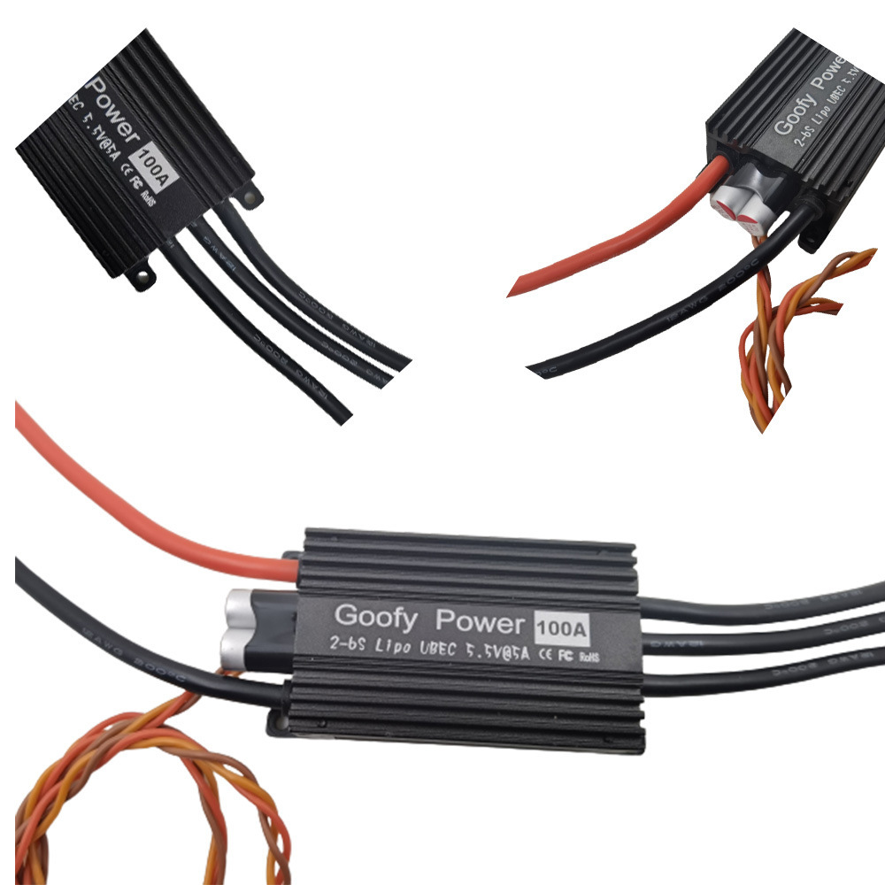
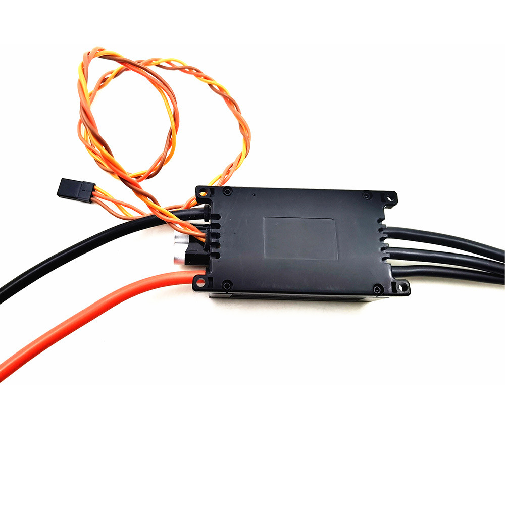
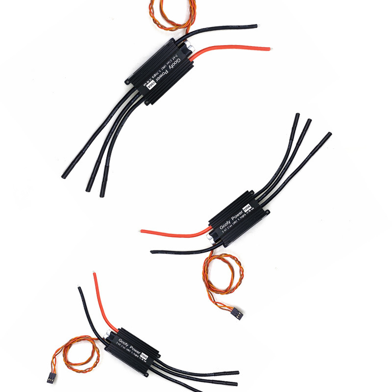
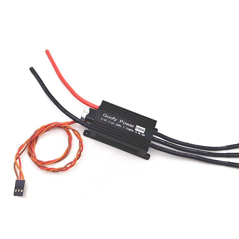
Wiring diagram

Operating instructions
1. Throttle stroke setting
When using the new remote control for the first time, set the throttle stroke. After setting, you can no longer set the throttle stroke. Setting method: turn on the remote control, turn the throttle to the highest point, connect the electric regulator to the battery, and the motor will sound the prompt tone of "7? 8 123", indicating that the power on is normal. Then the electric regulator will detect the number of battery cells, and several batteries will make several "drops". At this time, if the throttle value is higher than 1800us, the electric regulator will enter the throttle stroke setting mode and make a "drop beep drop" sound, After two sounds, pull the throttle to the lowest point and wait for the motor to make a "beep drop beep" sound. Then, after the throttle stroke of the motor is set, it emits two beeps and enters the waiting start state
2. Remote brake setting
Place the accelerator in the middle position, and then turn on the electric regulator. After one series of sound is completed, enter the setting when there is an uninterrupted single sound cycle. Then pull the remote lever to the high position (indicating opening the brake), pull it to the low position (indicating closing the brake) and stay. Then one series of sound is completed, complete the function setting, and then pull the remote lever down, Send out 2 short sound signals to confirm the sound and enter standby. At this time, the remote lever motor starts to rotate
3. Normal startup process
Connect the electric regulator according to the wiring diagram, push the remote lever of the remote controller to the lowest throttle position, turn on the remote control power supply, and then turn on the battery power supply. The motor will sound "? 7? 8 123" to indicate that the power on is normal. Then the electric regulator will detect the number of batteries, and several batteries will make several "drops", and then make two drops to enter the standby state, At this time, push the accelerator rocker to start the motor
4. Standby sound:
After entering the standby mode for 20 seconds, the electric regulator will send out the standby prompt tone "Di Du Di"
Ring every 5 seconds to remind the user that the battery is currently connected. This state will not affect the user's use
fault analysis
Dropping ~1 sound: low voltage protection occurs
Drip ~ drip ~ 2 sound: overheating protection
Drip ~ drip ~ drip 3: signal loss occurs
Tit ~ tit ~ tit ~ tit ~ 4 tones: startup failed
When the controller makes an error during operation, it will make a sound on the motor. The fault will not be saved. The error causes shutdown. After power failure and reset, the fault alarm sound will be cleared.
Safety instructions
Due to the powerful power of the brushless power system, incorrect use may cause personal injury and equipment damage. Please operate safely according to the instructions.
1. Do not operate the battery under voltage for a long time, which will affect the service life of the battery and reduce the efficiency of the governor.
2. Do not operate for a long time after the governor is overheated, otherwise it is easy to cause the damage of MOS tube and the damage of governor.
3. Please pay attention to the state of the motor and do not continue to operate when the motor is stuck by foreign objects, otherwise the service life of the motor and governor will be reduced.
4. Do not put the governor in overpressure state, otherwise the service life of the governor will be affected
5. When connecting the power supply, make sure there is no object within the rotation range of the propeller.
6. Use the speed regulator without danger.
7. Damaged regulators (e.g. broken or damaged due to reversed electrode connection and moisture) must not be used again. Otherwise, failure will occur or the purpose will not be achieved.
8. ESC can only be powered by battery and cannot be powered by power supply equipment.
matters needing attention:
1. If the motor rotates in the wrong direction, you can exchange any two wires of the three wires of the motor.
2. Only clean and tight metal connectors can be used to connect the motor and battery. It is better to use 5.5m/6mm PK connector. Pay attention to the positive and negative poles of the battery connector and do not connect them reversely. Replace the oxidized or loose plug or socket, because only the tight connection device can ensure high current and protect the speed controller from high voltage hazards and interference.
Note: the reverse connection of the positive and negative poles of the battery will cause serious damage, and the company does not guarantee it.
3. If there is a cry or other abnormal sound during acceleration, the angle of entry should be increased. If the angle of advance can not be improved by increasing to 30 °, your motor will be overloaded. At this time, use a smaller propeller or reduce the voltage, or replace a motor with better performance. If you hear two repeated beeps when the motor stops working, it means that the voltage of the battery is lower than the set value. The cut-off voltage of each battery can be adjusted to 2.9v or 3.0V. If it cannot be improved, it may be that the battery is dead or the discharge is insufficient. It may also be that the wire is too long, too thin, or the connector fails.
4. Between the brake and the starting point of the motor, the accelerator remote lever needs a small swing space. You can start by extending the two scale dents at the remote position of the throttle lever or fine-tuning upward, but it is not enough to refuel.
5. If it is not set as automatic angle advance, it can be set according to the following guidelines.
Inner rotor 0 to 12 °
Outer rotor 18 to 30 °
If your motor manufacturer has recommended motor angle, it is best to use it according to the angle guide given. Basic rule: the greater the angle, the greater the rpm and full throttle power.
The following are the parameters set by default.
-Turn off the brakes
-Inertia coast off
-PWM frequency = 16 kHz
-Starting power = 30%
-Low voltage protection = slow shutdown